
 English
 Español
 عربى
عربى русский
Contact Us
Your email address will not be published. Required fields are marked *
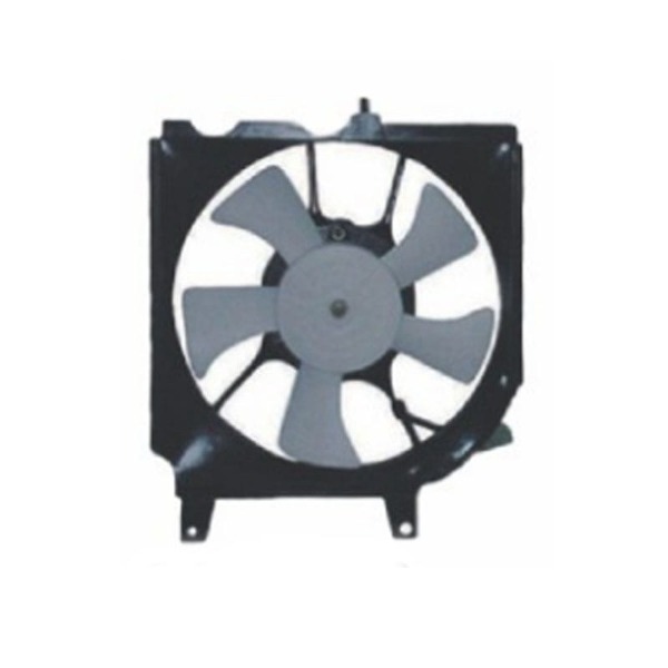
A 190mm low-noise EC fan carrying an IP55 rating occupies a narrow but demanding corner of the cooling market. The frame is large enough to move meaningful air through a condenser stack, a battery enclosure or a sealed electrical cabinet, yet small enough to fit inside a 200mm mounting envelope. Electronically commutated drive electronics deliver stepless speed control at efficiencies that a shaded-pole or capacitor-run motor cannot approach, and the IP55 rating allows the same hardware to survive washdown bays, dusty job sites and humid engine compartments.
Engineers rarely arrive at this specification by accident. It usually appears after an AC fan has failed a noise target, after a brushed DC fan has worn through its brushes, or after an open-frame fan has ingested water. Understanding what each element of the specification controls, where the elements reinforce one another and where they conflict is what separates a fan that runs quietly for ten years from one that howls, corrodes or seizes in its first season.
This guide works through the engineering behind a 190mm low-noise EC fan with IP55 protection: motor topology, sealing strategy, fan curve interpretation, impeller selection, mounting practice, control interfaces and the verification steps that prove the specification was actually met in production.
Each part of that description fixes a different set of design decisions, and each one is confirmed by a different test. Treating them as a single marketing label is the most common source of disappointment at the prototype stage.
| Element | What it fixes | Typical working range | How it is confirmed |
|---|---|---|---|
| 190 mm frame | Impeller diameter and mounting envelope | 190 mm nominal impeller, roughly 200 to 215 mm across the flange | Dimensional drawing and hole pattern |
| Low noise | Acoustic output at the intended duty point | About 45 to 58 dB(A) at one metre for a 190 mm EC fan at mid speed | Sound pressure measurement in a semi-anechoic room |
| EC motor | Commutation method, efficiency and control interface | 24 V or 48 V DC input with an integrated three-phase drive | Bench test of efficiency and speed control |
| IP55 | Resistance to dust and to low-pressure water jets | Dust protected and jet protected, not submersible | IEC 60529 test with the fan mounted as in service |
Sealing a fan traps heat. A gasketed housing, a potted control board and a sealed shaft path all reduce the surface area available for convection, so the motor and its electronics run warmer than in an open-frame design. Because magnet strength and winding resistance both drift with temperature, a sealed 190mm EC fan has to be dimensioned with that derating already applied rather than discovered on the test bench.
Lower noise usually means lower speed, and lower speed always means less airflow at the same pressure. A 190mm impeller has a fixed hydraulic ceiling: at a given static pressure it can only deliver so much air, no matter how much current the drive is willing to supply.
Sealing raises internal temperature, and quiet running lowers airflow. A 190 mm frame only resolves those conflicts when the duty point is defined before the fan is chosen.
When an acoustic target and a thermal target cannot both be met by a single fan at reduced speed, the practical answer is usually two fans running at moderate speed rather than one fan running flat out. Two units also provide redundancy in applications where a stalled fan means a derated system.
Noise in a fan comes from two families of sources: aerodynamic noise generated by the blades, and mechanical or electrical noise generated by the drive. Motor topology has almost no influence on the first and a great deal of influence on the second.
A brushed DC motor makes noise at every brush pass, produces a broadband hiss from arcing and sheds conductive dust inside the housing. An AC induction motor supplied from the mains carries torque pulsation at twice the line frequency, and when its speed is trimmed with a resistor divider or a phase-angle controller the distorted waveform adds a low-frequency hum that is difficult to damp. An EC motor replaces all of this with a three-phase inverter that switches well above the audible band and shapes current sinusoidally, leaving a torque output that is nearly free of ripple.
Because the drive sets the speed electronically, an EC fan can be mapped directly to a temperature sensor or a control signal. The fan then runs only as fast as the thermal load requires, and it spends most of its life below the speed at which blade noise becomes the dominant contributor. Real installations frequently see a five to ten dB(A) reduction at part load compared with a fixed-speed AC fan that must be sized for the worst case.
| Motor type | Typical efficiency in small fans | Speed control | Dominant noise source |
|---|---|---|---|
| AC induction or shaded pole | Roughly 30 to 50 per cent | Voltage trimming, limited steps | Line-frequency hum and bearing noise |
| Brushed DC | Roughly 60 to 75 per cent | Voltage or PWM control | Brush arcing and commutation ripple |
| EC brushless DC | Roughly 75 to 88 per cent | Stepless, signal or bus controlled | Aerodynamic noise from the impeller |
The efficiency gap matters beyond energy consumption. Losses that are not converted into mechanical work become heat inside a sealed housing, and heat is exactly what an IP55 enclosure cannot easily reject.
IP55 comes from IEC 60529 and it is made of two separate digits. The first digit, five, means dust protected: a limited quantity of dust may enter, but it must not interfere with operation or safety. The second digit, five, means protection against water jets from a 6.3 mm nozzle delivering roughly 12.5 litres per minute at about 30 kPa from a distance of about three metres for at least three minutes. Neither digit promises a dust-tight or submersible product.
A sealed enclosure still breathes through temperature cycles. Water vapour migrates in, then condenses on cold surfaces after shutdown, and the resulting film sits directly on the control board. The countermeasures are a correctly placed breather membrane, a drain channel at the lowest point of the installed orientation, and a coating on the electronics. An IP55 fan that passed the laboratory test can still fail in the field if it is mounted upside down with the drain path above the motor.
A fan does not deliver a fixed airflow; it delivers whatever airflow the system resistance allows. Selection means placing the intersection of the fan curve and the system resistance curve inside the stable, efficient part of the fan map, then checking that the acoustic and electrical data on the datasheet belong to that same intersection.
Datasheet curves are measured on a test plenum that is not your enclosure. Inlet obstructions, a tight bend a few centimetres from the guard, a fouled coil and a filter loading up over time all move the system curve to the left. A reasonable rule is to select a fan whose free-delivery airflow is at least twenty to thirty per cent above the calculated requirement, then use the speed control to trim back to the real operating point.
For a 190mm frame, a backward-tilting centrifugal impeller driven by an integrated EC motor is the configuration that most often satisfies both a pressure requirement and a noise target at this size, because the wheel converts rotational speed into static pressure without the strong blade-passing tone of an axial design.
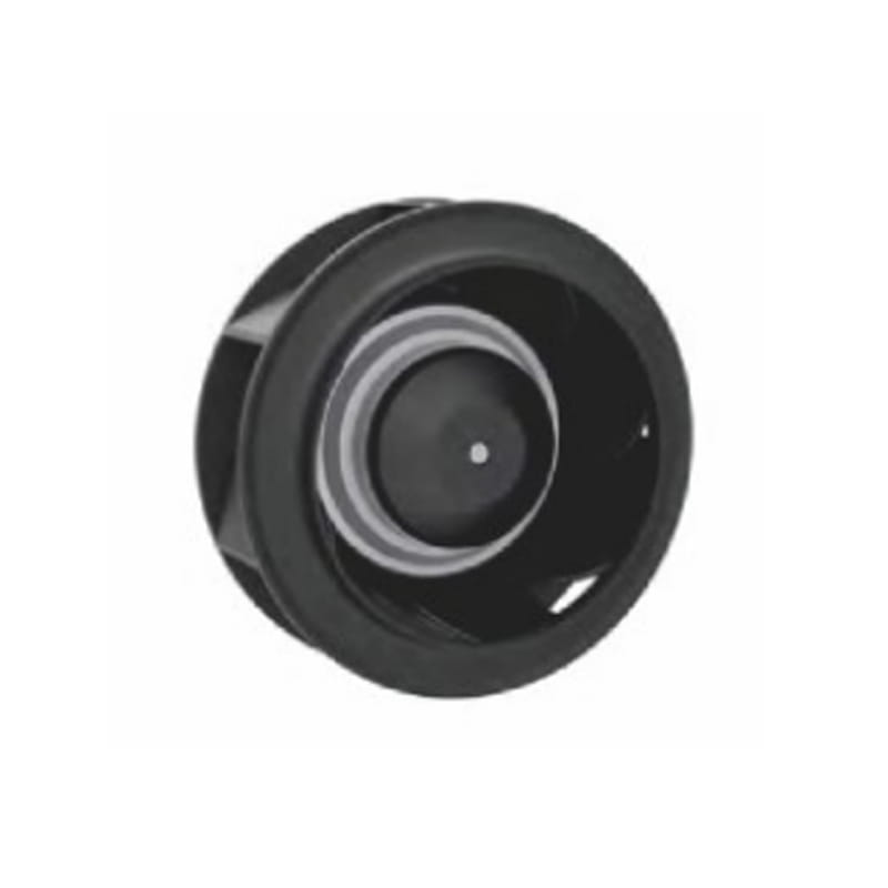 EC72-B190 EC Backward Tilting Brushless Centrifugal FanSpecification ARTICLE. NO EC Backward Tilting Centrifugal Fan Voltage 220/230V (support customization) Wind of ≥105W Applicable Reversible universals Current ≤0.87A Tu...View Product →
Confirm three numbers before locking a selection: the pressure at the duty point rather than at free delivery, the speed at which the published sound level was measured, and the input power at that same operating point. Suppliers occasionally quote quiet figures taken at half speed alongside airflow figures taken at full speed.
At 190mm the choice of impeller matters as much as the choice of motor, because the wheel decides the shape of the curve, the position of the best-efficiency region and the character of the noise.
| Impeller type | Pressure characteristic | Noise character | Typical duty at 190 mm |
|---|---|---|---|
| Backward-curved centrifugal | High static pressure with a stable curve | Lower tonal content, wide usable range | Condensers and ducted cabinet cooling |
| Forward-curved centrifugal | High airflow at low pressure | Stronger broadband level from the compact casing | Evaporator and blower duty |
| Axial | High airflow, low pressure | Blade-passing tone dominates the spectrum | Radiator and open-panel cooling |
Related designs in the same family, such as a DC brushless centrifugal fan built around a forward-curved wheel, trade pressure capability for a shallower casing and a wider inlet. That trade is sensible when the system resistance is dominated by a short, open duct rather than by a dense coil.
If the calculated duty point sits above what a 190mm wheel can produce at an acceptable rotational speed, resist the temptation to overspeed it. Stepping up to a 225mm EC centrifugal fan recovers airflow at a lower speed, which usually reduces both noise and bearing load. The cost is a larger mounting envelope, a heavier unit and a revised mounting pattern.
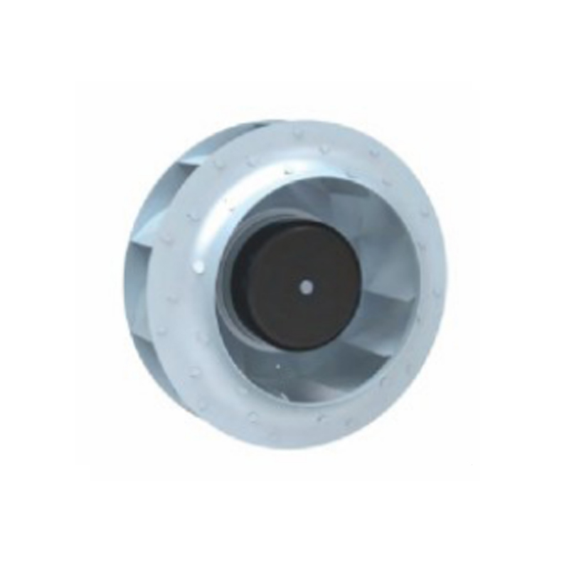 EC92-B225 EC Radiator Backward Tilting Centrifugal FanSpecification ITEM. NO EC backward-tilting centrifugal fan Voltage 220/230V(Support customization) Wind from ≥135W Applicable Universal Reversible Current ≤1.05A Turn ...View Product →
Frame size and impeller diameter are not the same dimension. A 190mm frame may house a slightly smaller wheel once the shroud clearance is accounted for, and that clearance affects both the delivered airflow and the noise level. Always compare wheels on diameter, not on the flange drawing.
Electrified vehicles have pushed fan specifications in a direction that suits EC technology. Battery packs and power electronics need cooling proportional to load, they need it with a very low acoustic signature at low speed, and they need hardware that tolerates humidity, road spray and continuous vibration. A 190mm low-noise EC fan with IP55 protection sits in the middle of that envelope.
Two design notes are worth carrying into any battery cooling programme. First, the fan is usually the least expensive component in the thermal loop and the easiest to change late, so specify the control interface early: a tachometer output and a fault signal are worth more than a small gain in peak airflow. Second, duty cycle matters more than peak performance. A fan that spends most of its life at thirty per cent speed will outlast one that is cycled to full speed every few minutes, because bearing grease migration and thermal cycling, not aerodynamic load, set the service life.
Where the pressure requirement is modest and the priority is moving a large volume of air across a radiator or a heat sink, a brushless axial fan is often the better match at the same voltage and with the same control interface. Axial units are also easier to arrange in arrays, which helps when redundancy is required.
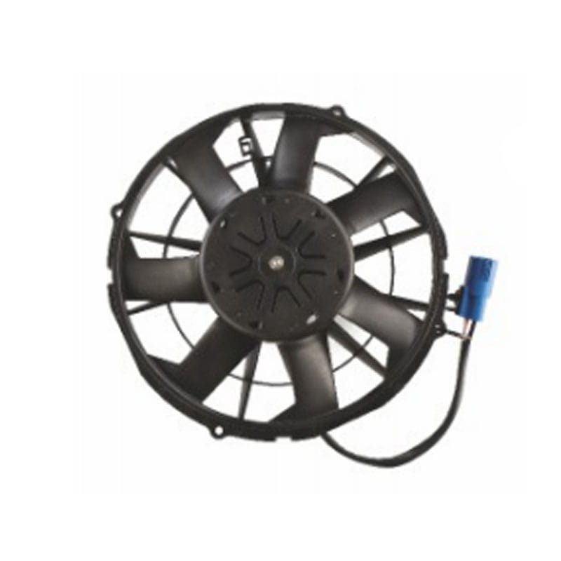 Specification ITEM. NO 12" built-in DC permanent magnet brushless drive fan Voltage 6-18V(Support customization) Wind from 3800m 3 /h Applicable Processing machinery, ...View Product →
Two fans with identical laboratory data can differ by ten dB(A) once installed. Most of that difference is created by the mounting arrangement rather than by the fan itself.
Sealing and mounting interact here as well. A gasketed fan is normally stiffer and heavier than an open-frame equivalent, which shifts its natural frequencies and can make a previously quiet panel resonate.
An EC fan is a small power electronics product, so the electrical specification deserves the same care as the aerodynamic one. The following items should appear explicitly in any purchase specification.
A practical habit is to test the fan with the harness and connector that will be used in production. A metre of unshielded cable can change the emissions signature far more than any change inside the fan housing.
The final question is not whether the sample works, but whether the specification survives the transition from prototype to volume. Four verification tracks cover most of the risk.
Suppliers with in-house EC fan and blower manufacturing normally hold winding tension, rotor balancing and end-of-line acoustic screening in one plant, which shortens the loop between a field complaint and a design change. For automotive and off-highway programmes, a registered quality management system and documented process capability on those three operations are usually the minimum commercial requirement, and they should be confirmed before tooling is released.
It covers two distinct risks. The first digit means the housing is dust protected, so a limited amount of dust may enter without interfering with operation. The second digit means the unit resists low-pressure water jets from any direction. It does not mean the fan is dust tight or that it can be submerged.
It can, but continuous full speed sacrifices the main benefit of the motor topology. Operating at sixty to eighty per cent of maximum speed usually keeps the duty point inside the stable region of the curve while cutting acoustic output and extending bearing life. Reserve full speed for upset conditions.
Because sound pressure depends on distance, mounting, inlet conditions and the speed at which the measurement was taken. A figure quoted at one metre with a clear inlet at half speed is not comparable with a figure taken at full speed inside a test plenum. Ask for sound pressure, distance, speed and mounting method together.
Because seals stop liquid water, not water vapour. Temperature cycling pulls humid air in through any equalisation path and pushes it back out again, and the vapour that remains condenses on cold surfaces after shutdown. A hydrophobic breather, a correctly oriented drain channel and a coated control board address the problem.
When the required duty point sits in the steep part of the curve and the noise target cannot be met at the speed needed. A 225mm EC centrifugal fan delivers the same airflow at a lower speed, which normally reduces both noise and bearing load, at the cost of a larger envelope.
It depends on the host system. A zero to ten volt analogue input is simple and robust for cabinet cooling, while PWM or a bus command suits vehicle platforms that already carry a network. In both cases, specify a tachometer output and a fault line so the controller can detect a stalled rotor.
Your email address will not be published. Required fields are marked *

Zhejiang Nicety Electric Machinery Co., Ltd. specializes in the production of four series of products: condenser electronic fan, radiator (water tank) fan, blower, and air conditioner assembly. Professional production American, European, Japanese, Korean And Domestic brand DC automotive axial fans.
Email: [email protected] / [email protected]
Tel: +86-0578-7125439 / +86 181 0658 9231
Address:No. 98, Guangda Street, Jinsha Industrial Zone, Longquan City, Zhejiang Province, China