
 English
 Español
 عربى
 русский
Contact Us
Your email address will not be published. Required fields are marked *
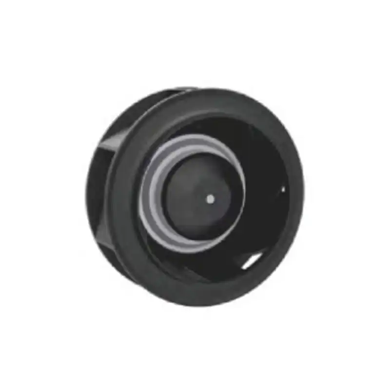
A 225mm EC cooling radial fan is a compact centrifugal air mover built around an electronically commutated motor and an impeller with a nominal diameter of 225 mm. Unlike an axial fan, which pushes air along the shaft axis, a radial fan draws air into the impeller eye and discharges it outward through a scroll or volute. That change in airflow path is the reason a 225mm EC cooling radial fan can deliver useful pressure against filters, dense heat exchangers, ducts, and space-constrained plenums.
The EC motor adds a second layer of practical value. It converts incoming DC power through integrated electronics, so the fan can be speed-controlled, monitored, and protected without an external drive. In equipment design, that combination matters more than a single airflow number. The fan becomes part of a thermal control system that must stay stable as filter loading rises, ambient temperature changes, and duty cycles shift.
Axial intake, radial discharge through a scroll. The housing shapes pressure and flow.
EC commutation replaces brushes with electronic switching and integrated control.
A 225 mm diameter balances pressure capability with enclosure space.
| Design feature | Practical consequence | What to verify |
|---|---|---|
| Centrifugal impeller | Higher pressure capability than many axial fans of similar size | Duty point on a system resistance curve |
| EC motor | Variable speed, monitoring, and protection can be integrated | Control input compatibility and fault behavior |
| 225 mm impeller | Fits many 250 mm class envelopes while moving meaningful airflow | Inlet clearance and scroll orientation |
| Volute housing | Discharge direction can be matched to ductwork or plenum geometry | Outlet transition losses and service access |
The 225 mm diameter is not a marketing number. It is a packaging compromise. A smaller impeller can fit into tight spaces, but it usually needs higher speed to move the same air, which can raise tonal noise and bearing stress. A larger impeller can move more air at lower speed, but it demands a larger scroll, more inlet clearance, and more room around the discharge. The 225 mm size often lands in the practical middle for compact cooling packages, especially where the fan must work against a real system resistance rather than an open bench.
Radial fans are chosen when pressure matters. A filter mat, a louvered inlet, a finned heat exchanger, and a short duct can each add resistance. If the fan cannot hold airflow as resistance rises, the thermal margin disappears long before the equipment reaches its rated load. A well-matched 225mm EC cooling radial fan is selected against the installed system curve, not against a headline free-air airflow figure. The useful question is simple: at the required pressure, how much airflow remains, and at what speed, sound level, and input power?
Blade geometry also changes the shape of the airflow and pressure curve. A backward-curved blade centrifugal fan design is often favored when stable pressure, lower noise, and better operating efficiency are priorities. Forward-curved impellers can move more air in a smaller package, but they may be more sensitive to inlet conditions and system resistance. The right choice depends on the thermal load profile, the available envelope, and the sound target.
An EC fan is not simply a DC fan with a different label. The motor uses electronic switching to control the stator field, and the electronics can shape start-up behavior, speed response, and fault handling. In a cooling system, that means the fan can follow a temperature signal, ramp gently instead of stepping, and report speed back to a controller. It also means the fan can be protected against locked-rotor current, over-temperature, and reverse polarity, depending on the design.
Many EC fans accept a control signal such as a 0 to 10 V input, a pulse-width modulation signal, or a simple internal speed curve. The control method should be chosen with the system controller, not after the fan is installed. A fan that ramps too aggressively can create audible speed changes and current spikes. A fan with a poorly defined minimum speed may stall in low-load conditions or fail to overcome filter resistance during start-up. The controller should define the start threshold, minimum stable speed, maximum speed, and fault response.
Because the electronics are inside or attached to the fan, thermal design must consider the motor driver as well as the impeller. Ambient temperature around the electronics, airflow over the motor housing, and connector orientation all affect long-term reliability. Voltage tolerance, inrush behavior, and electromagnetic compatibility should be checked in the complete assembly. A fan that performs well on a bench can behave differently when it is mounted against a panel, surrounded by heat sources, and powered through a long harness.
| System requirement | EC fan behavior to confirm | Risk if overlooked |
|---|---|---|
| Temperature-based speed control | Stable minimum speed and predictable ramp | Audible cycling and unstable thermal response |
| Low-voltage operation | Start-up and running performance at voltage extremes | Failed restart or reduced airflow |
| Fault monitoring | Speed signal, alarm output, or locked-rotor protection | Silent cooling failure |
| Electromagnetic compatibility | Harness routing and filtering in the final assembly | Control interference or sensor noise |
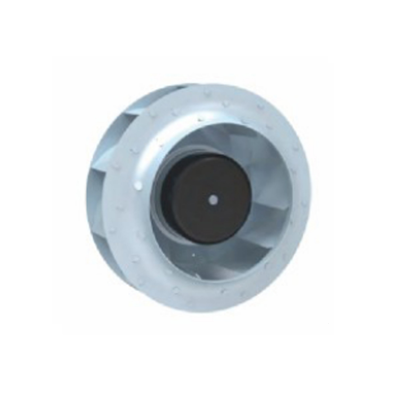 EC92-B225 EC Backward-Tilting Centrifugal Fan for Radiator CoolingEC-controlled backward-tilting centrifugal fan for automotive heat dissipation, with adjustable speed and reversible operation; check motor-driver thermal and system-resistance requirements during selection.View Product →
Selection starts with the enclosure, not the catalog. Define the heat load, allowable temperature rise, altitude, ambient temperature, filter type, inlet and outlet restrictions, and expected duty cycle. Then estimate the system resistance curve. The fan should be selected where its pressure-flow curve crosses the system curve with enough margin to cover filter loading and production variation. A fan that only meets the duty point on a clean filter is a maintenance problem waiting to happen.
For a compact thermal package, a 225 mm backward-tilting EC centrifugal fan is often a practical candidate because it can produce useful pressure without an excessively large scroll. A forward-tilting unit may be preferable where higher airflow is needed in a smaller package and the system resistance is modest. The decision should be based on measured or estimated system data, not on the impeller alone.
 EC72-B225 EC Backward-Tilt Centrifugal Cooling FanCustomizable 225 mm EC centrifugal fan for heat-dissipation systems, with adjustable speed and reversible control; installation and inlet/discharge path design affect practical cooling performance.View Product →
| Parameter | Why it is critical | Practical check |
|---|---|---|
| Static pressure at duty point | Determines whether airflow survives filters and ducts | Overlay fan curve and system curve |
| Input voltage range | Affects start-up, speed stability, and current draw | Test at minimum and maximum supply |
| Control signal | Sets compatibility with the thermal controller | Confirm thresholds, polarity, and fault response |
| Sound quality | A tonal fan can be more noticeable than a louder broadband fan | Measure at several speeds and listening positions |
| Mounting orientation | Changes inlet conditions and bearing load | Validate in the final mechanical assembly |
A 225mm EC cooling radial fan can lose a significant part of its performance through poor installation. The impeller needs a clean inlet path. The discharge needs a transition that does not create sudden expansion or sharp turns. The mounting structure must isolate vibration without allowing the fan to move into the shroud. Service access must allow filter replacement and fan inspection without removing the entire thermal module.
maximum vibration.| Installation issue | Likely effect | Correction |
|---|---|---|
| Inlet too close to a panel | Reduced airflow and higher noise | Increase clearance or add a bell-mouth inlet |
| Abrupt outlet expansion | Pressure loss and turbulence | Use a gradual transition or short diffuser |
| Rigid mounting to a thin panel | Structure-borne vibration | Add isolation mounts and stiffen the panel |
| Harness across the inlet | Flow disturbance and tonal noise | Reroute and secure the harness |
Validation should reproduce the installed environment closely enough to reveal interactions. A bench test with open inlet and outlet is useful for screening, but it is not a release test for a ducted or filtered system. The fan should be tested with the production filter, the production harness, the production mounting structure, and the expected control signal. Thermal soak testing should continue long enough for the motor electronics and bearing system to reach stable temperature.
| Validation area | What to measure | Release question |
|---|---|---|
| Airflow and pressure | Duty point across filter loading states | Is thermal margin maintained at end of service interval? |
| Control response | Start-up, ramp, minimum speed, and fault recovery | Does the fan remain stable with the real controller? |
| Acoustic behavior | Sound pressure at several speeds and microphone positions | Are tonal components acceptable in the product context? |
| Vibration and mounting | Structure-borne vibration and visual clearance | Will wear or misalignment occur over time? |
| Environmental endurance | Temperature, humidity, dust, and voltage extremes | Does performance remain predictable after exposure? |
Acoustic validation deserves special attention because a 225mm EC cooling radial fan can produce both broadband noise and tonal noise. Broadband noise may be acceptable if it is smooth and low level. A narrow tone at a specific speed can be far more noticeable, even when the overall sound level looks reasonable on a meter. Speed sweeps are useful because they reveal resonances in the fan, bracket, panel, or duct. If a resonance appears, change the mounting stiffness, add damping, or shift the operating speed range.
Technical selection is only half of the decision. A cooling fan is a long-life component that affects warranty exposure, service cost, and product reputation. Procurement and quality teams should ask how the motor, impeller, and electronics are controlled in production, how change notifications are handled, and how traceability works. For automotive and off-highway applications, the supplier should be able to explain its quality management system, production approval process, and deviation control without relying on broad claims.
| Question | Why it matters | Evidence to request |
|---|---|---|
| Is the motor and fan integration controlled in-house? | Affects consistency and corrective action speed | Process flow and key inspection points |
| How is impeller balance verified? | Influences vibration, bearing life, and noise | Balance records and sample audit plan |
| How are electronics protected during assembly? | Prevents latent failures in the field | Handling controls and test coverage |
| How are design or material changes communicated? | Protects validated thermal and acoustic performance | Change notification and requalification rules |
| What is the service life basis? | Sets maintenance and warranty expectations | Life test summary and duty cycle assumptions |
A supplier that can discuss airflow, pressure, control, and production control in the same conversation is usually easier to integrate than one that offers only a catalog page. The goal is not to collect documents. The goal is to confirm that the selected 225mm EC cooling radial fan will behave the same way in production as it did during validation.
Most cooling problems appear after the fan is chosen. They come from installation details, control settings, or validation shortcuts. The list below covers mistakes that are common enough to check on every project.
| Mistake | Consequence | Better practice |
|---|---|---|
| Selecting at free-air airflow | Airflow collapses under filter or duct resistance | Select at the installed duty point |
| Ignoring inlet clearance | Noise rises and pressure falls | Model the inlet path and test the final assembly |
| Using a simple on-off control | Thermal cycling, current spikes, and audible steps | Define ramp and minimum speed with the controller |
| Testing only a clean filter | No margin at the end of the service interval | Test at clean, half-loaded, and loaded states |
| Treating sound level as one number | Tones and resonances are missed | Use speed sweeps and multiple measurement positions |
The correction is usually not a larger fan. It is a more honest system model, a cleaner inlet, a better outlet transition, and a control strategy that respects the fan's stable operating range. A 225mm EC cooling radial fan can be a highly effective thermal component when these details are designed together.
It is used where compact size, pressure capability, and controllable airflow are needed. Typical uses include electronics enclosures, heat exchangers, filter boxes, compact thermal modules, and equipment that must maintain cooling as resistance rises.
A radial fan can produce higher pressure in a compact scroll, which helps when air must pass through filters, fins, or ducts. An axial fan may be preferable when low pressure and a thin mounting profile are the main priorities.
No. A larger impeller may move more air at lower speed, but it needs more space and a suitable scroll. The benefit depends on the system resistance, inlet clearance, acoustic target, and the actual duty point.
The choice depends on the system controller. Common options include an analog voltage input, a pulse-width modulation signal, or an internal speed curve. The important checks are start threshold, minimum stable speed, fault response, and compatibility with the harness.
Test it in the final mechanical assembly with the production filter, harness, and control signal. Measure airflow and pressure at several resistance states, check start-up and fault behavior, and perform acoustic speed sweeps to reveal tones or resonances.
Restricting the inlet or placing the fan too close to a panel. That single mistake can reduce airflow, raise noise, and make a correctly selected fan appear inadequate.
Your email address will not be published. Required fields are marked *

Zhejiang Nicety Electric Machinery Co., Ltd. specializes in the production of four series of products: condenser electronic fan, radiator (water tank) fan, blower, and air conditioner assembly. Professional production American, European, Japanese, Korean And Domestic brand DC automotive axial fans.
Email: [email protected] / [email protected]
Tel: +86-0578-7125439 / +86 181 0658 9231
Address:No. 98, Guangda Street, Jinsha Industrial Zone, Longquan City, Zhejiang Province, China